Tips for Making Flexible PCBs Durable in Harsh Environments
Making Flexible PCBs Durable in Harsh Environments
With its ability to save space, reduce weight and withstand harsh conditions, rigid flex PCBs are a popular choice in many industries like aerospace and defense, medical, automotive, consumer electronics and wearables. However, the question is: can flexible PCBs really stand up to a lot of abuse? The answer is yes, if you follow some tips and take the right steps during your design process.
The conductive copper used in a flex circuit is usually coated on both sides by a thin layer of dielectric material called an overlay. This insulating layer protects the copper from oxidation. It also helps to maintain the structural integrity of the flex circuit. The flex overlay is typically a polyimide film. Polyimide is a tough, durable material that is resistant to chemicals and high temperatures, making it an excellent choice for a flex circuit layer stack.
During the lamination process, the copper and overlay layers are glued to the polyimide with an acrylic or epoxy adhesive. The resulting laminate is then subjected to a thermal cycle. This heat process allows the flex circuit to withstand a lot of bends and flexes without breaking down or deteriorating. Integrate reinforcement elements such as stiffeners or adhesives in critical areas to enhance mechanical strength and prevent flexing beyond specified limits.
Another key factor in a flexible pcb durability is its ability to handle stress points. Stress points are areas where there is an abrupt transition from one thickness to the next, such as a wide trace connected to a narrow one. To prevent stress points, it is important to use a gradual transition between the different layers.
Tips for Making Flexible PCBs Durable in Harsh Environments
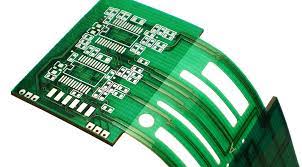
The most common flex PCBs are single-sided, but double-sided flex circuits are available as well. These types of flex circuits have a conductive copper layer on each side of the dielectric layer, and metalized holes connect these two traces. They can handle multiple bending cycles and a lot of stress, making them an ideal option for harsh environments.
A flex PCB can be made even more durable by adding stiffeners to the flex-to-rigid interfaces. These help to relieve strain and balance the weight, while enhancing abrasion resistance and improving flex-to-rigid adhesion. Another way to make a flex PCB even more durable is to add an electromagnetic interference (EMI) shielding film, similar to the metal houses added to rigid boards.
A flex circuit’s ability to withstand harsh environments is dependent on how it’s designed. It’s important to consult with your CM and PCB/layout provider for guidelines and standards, and to pay attention to the environment in which the board will be used. A few other tips: Opt for high-quality, durable materials specifically designed for flexible PCBs. Polyimide (PI) substrates offer excellent flexibility and temperature resistance.
Strategically place components to minimize stress on the flexible areas. Avoid sharp bends and ensure components are secured properly to withstand vibrations and shocks. Encapsulate the flexible PCB with a protective coating to shield it from moisture, chemicals, and mechanical damage. Materials like silicone or polyurethane provide reliable protection.